Step 2 – Assembly of Main Body
Step 3 – Installing Electronics
Introduction
Thanks for your purchase of my DC-17m 3D print files. I’ve put an insane amount of time into this project, so please do not share these files or sell prints to others. Instead, please direct people to purchase directly from Etsy. Your help in making this happen will ensure that I’m able to provide you with the best possible support here.
A word of warning: Loctite is some awesome glue, and when dealing with small parts, you’re in danger of gluing some fingers together. I’ve had some close calls myself. Proceed at your own risk.
Great to build with you!
Kyle Gilbert
Basic Parts
This list includes items that you’ll need to purchase even if you’re not interested in adding complete electronics.
- Black filament for everything that’s not transparent.
- Transparent blue filament For the “window” or “win” components.
- Magnets for holding attachments and clips.
- Hinge for side door
- .5” wooden dowel – cut to 6.5” length for sniper barrel. Alternately, you can use a piece of .5″ electrical conduit.
- .25” metal rod – cut to two 10” lengths for sniper rails.
- Spring for trigger
- Glue (this stuff dries quickly, bonds PLA well, and )
- Black spray paint
- Red spray paint (for the details on the grenade launcher)
- Small screws (2 packs)
Electronic Parts
This is a beautiful kit, even without electronics, but for those brave people who are willing to work a soldering iron to add electronics, you’ll need the additional parts:
- Electronics from TRamp (not cheap, a wait time of several months, and shipping from the UK). If you do order from him, you’ll want to mention the following in your order: “Start up with DC-17m, no rotary, no laser, no LED strip. Please add blaster, sniper, grenade, and anti-armor sounds.”
- LED strip connectors for getting a good connection for your wiring to LED strips.
- Switch (you only need one of these, for the grenade, so you may want to look for a single pack)
- Battery connector
- Power button
- LED Strip lights
- 2-pin connector (male) – need 1
- 2-pin connector (female) – need 2
- 4-pin connector (male) – need 1
- 4-pin connector (female) – need 1
Rather than building out full electronics, you can add some lights by doing the following:
- purchase the power button, the LED strip lights, and the battery, and the connectors. Cut off a strand of about 8-10 lights, and wire together to provide illumination from the core to the top window. See diagram below.

Step 1 – Print All Parts
Parts are not aligned for best 3D printing, so you will need to assess each part and add supports as needed. A few notes on printing:
- I typically print with three outside and top and bottom layers for added strength.
- Begin with printing main1, main2, and main3, then core-cover, bottom-handle, and front-handle.
- Main1 – I print as is with supports.
- Main2 – I print with the front side down with supports.
- Sniper attachment – I print with the angled back side down without supports.
- Blaster attachment – I print with the angled back side down without supports.
- All parts that include the word window should be printed in the transparent blue filament, even if you’re not including electronics.
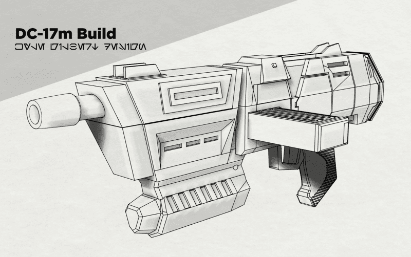
Step 2 – Assembly of Main Body
Magnets – Before you start putting things together, you’ll want to use the Loctite to glue in magnets (in the attachments, core cover, clip slot, clips, and butt of the gun (main3).
- It’s REALLY important that you have the magnets pointing the right way, or you’re going to have some major problems.
- My method is to stack up my magnets on a piece of metal so that they’re all aligned in the same way.
- For all magnets on core-cover and main2, I glue these bottom side down.
- For all magnets on the attachments, clips, and main3, turn the magnet upside down.
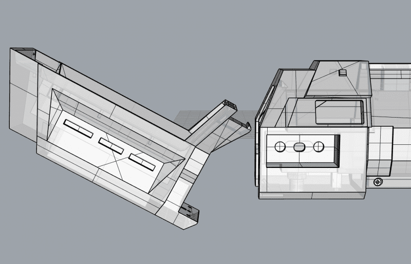
Connect Main1 to Main2: Slide the hook end of Main1 up into Main2. You’ll want to make sure that the hook is pressed up tight into that spot before you start angling the bottom over. If it hangs any, that means the hook isn’t in there far enough, so push it up again before swinging the bottom into place.
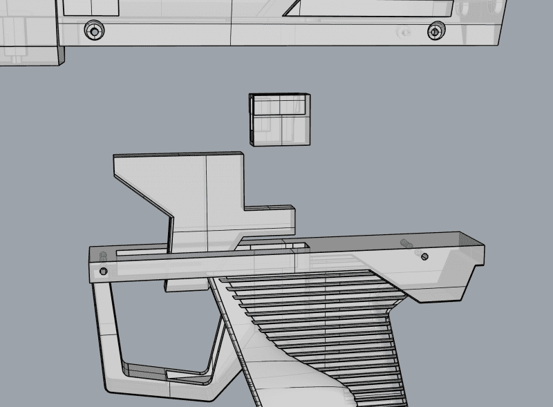
Connecting Bottom Handle: Use Loctite around the edge, and glue together main1 and bottom-handle.
Connecting Main Handle: First insert the trigger, then put the spring in the gap created between the trigger and the rest of the handle. If you’re not installing electronics, you can glue the trigger mechanism part in place, to holding the spring and trigger in place (but make sure that you don’t accidentally glue the trigger in place – only put glue on the sides and back).
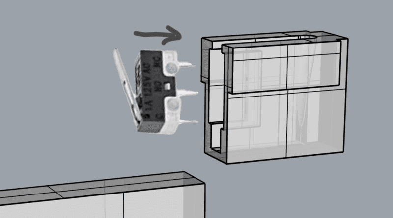
If you’re installing electronics, you need to first slide the electronic trigger switch – the one attached to TRamp’s electronics kit – into the trigger mechanism.
Secure the main handle to main 2 with four screws. Do not glue in place.
If you’re installing electronics, you’ll see a small button that’s used to cycle through weapons and reload the ammo. to install this part:
- You’ll want to remove main1 so that you can get better clearance.
- You’ll need to glue the bottom of this button to the small tip of the part called selector-plug.
- Once that’s dry, you’ve got a tricky part to install and you’ll want to practice things before adding a small amount of glue to the narrow sides of the selector plug and pushing it down the small square hole inside main 2. You’re not done until you can see the small button sticking out the bottom. Wait till this dries before working on anything else.
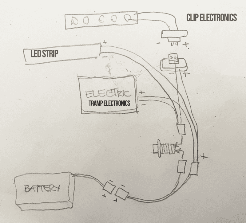
Step 3 – Installing Electronics
This section only applies if you’re building out the blaster with full electronics. I will work on providing a video overview of installing the electronics, but for now, this diagram will show the overall setup:
- The LED strip below is installed on Core-LED-holder, which is glued to the bottom of core cover.
- The female 2-pin electrical connector from digikey must be glued inside of main2 so that the connectors are peeking out the hole where the clips connect.
- I like to build things out so that the battery sits directly inside of main3 for easy access to the battery.
- In order to pass an electrical connection to the blaster barrel LED, I cut that four-line cable and solder each side to a 4-pin connector. The female connector glues to the bottom of the core cover. The male connector glues inside the blaster attachment. You just need to make sure that you keep this cord aligned the same way, not reversed.
Step 4 – Attachments
Fortunately, attachments are fairly straightforward.
- The blaster-muzzle glues to the blaster attachment.
- The blaster-attach-win are printed in blue filament and are inserted into the slits in the blaster attachment. I add a little glue with a glue gun inside to hold those in place.
- The sniper-front1 glues to the piece of dowel or conduit, and that glues into sniper-front2. Sniper-front2 glues into the sniper attachment.
- Sniper rails are glued into sniper-front2, rail fronts (need 2) are glued into place on the rails. Then, rail-backs are test fit onto the back of the sniper rails and then are glued to the sides of the sniper attachment.
- Grenade-attachment-back is glued to the back of the grenade launcher attachment, making sure that the parts are correctly aligned on the inside so that the grenade can slide in.
Revisions
- 9/6/21 – full instructions moved to the website.